I've been wanting to share the process of how the guitar pedals I build go from idea to finished product. All the pedals I've built, with the exception of the one I built for my brother, are built for my own use and are not production models, nor are they production quality. This is simply a hobby that I enjoy, and hopefully will continue to enjoy for some time to come. I felt that if anyone out there came across this blog and were interested in starting the hobby, or wanted to acquire a little more knowledge to streamline their own process, perhaps I could shed a little bit of insight and help them out.
Initial Planning
The very first pedal I ever built was a Bazz Fuss, followed by a few variants after that. Since then every pedal I've built started off as a question. What type of effect(s) do I want, or feel that I need, or even want to try out but can't afford the genuine version? I had always wanted a tube screamer style pedal, and although the genuine thing and its many clones are ubiquitous, I decided I would take more pride in having built my own. I searched around online for a tube screamer layout and the first website to popup was tagboardeffects. I searched their extensive library of layouts and chose the tube screamer that I felt the most comfortable building and got started.
Cutting the Board
This part is fairly straight forward, depending on how big the layout requires the board to be. I usually use stripboard, which is a thin fiberglass board with strips of copper adhered to it. I've tried some other stuff and only ever had slight success with it, but much frustration, so I've stuck to stripboard as my main circuit board material. From here I will count out how many holes the layout requires, both horizontal and vertical. I do this with a toothpick, believe it or not, and I count out each way two or three times before I mark it with a sharpie, just beyond the required length. Once I am satisfied that the dimensions are correct I use wire cutters and snip along the row of holes just beyond where I marked. Sure, you lose a row of material, but it's better than making a mistake and needing to cut a whole new board. From there I'll snip off any rough edges, sometimes even using sandpaper for further adjustments where needed. Measure a hundred times, cut once!
Many layouts will require you to cut the traces on the board to reroute the signal of components on that row to somewhere else. I use the same toothpick method as I do for getting the board down to the right size here too, and I will then mark that hole with a sharpie and then count it off a few more times to make sure I've marked the right place. I usually reference the layout image and count both horizontal and vertical holes in all directions to make sure this one spot is where the trace cut needs to be. Once all the trace cuts have been marked and verified I use a step drill bit in a screw driver handle that uses interchangeable bits. With firm, but not too firm, pressure I place the tip into the hole and twist until I see fiberglass dust. I then blow the dust away and see if the trace looks properly severed. Once all traces have been cut, I use a multimeter to make sure there is no current being passed beyond the trace cuts. I then use an xacto knife and clean up around the hole, to make it less likely to be bridged while soldering.
Collecting Parts
All guitar pedal circuits are made up of components, usually consisting of: resistors, capacitors, diodes, transistors, JFETs, op amps, and other ICs. I like to bag up my parts in little bags and write on a small piece of tape what the build is going to be. I start off with the lower laying parts, such as resistors and diodes. These components are the ones I solder onto the board first, so I like to find them first. Then I find the capacitors, then any transistors or JFETs and from there I wait until the main board is built to even think about op amps or ICs. I usually find these parts from old electronics, but I do have a collection of new parts just in case the old electronics I have can't yield the parts that I need. I will reference a part with online sources to make sure I am collecting the correct value. Resistors will have colored stripes that will calculate the value. Capacitors often have their code as well, for example 104 on a capacitor means that capacitor is 100nf (nf meaning nanofarad). Other components will also have their markings, so if you have any questions check online to cross-reference the component's code/markings to make sure it is what the circuit requires. A little wiggle room, or tolerance, is allowed on parts so don't be afraid to substitute something fairly close with what is required by the layout.
Populating the Board
Now that the board is cut, the parts are bagged and the soldering iron is hot, it's time to start soldering everything together. I start off with the links, which are simply thin pieces of metal, often the leftover legs I've cut from the underside of installed components. These are used to replace the traces we cut previously, and are the lowest laying aspect on the board. Then I start placing the components in a grid pattern, much the same way I used to cut the board. I start off with resistors and diodes, paying very close attention to the polarity of the diodes in the layout and how I place them on the board. Once I've made sure I've placed all the resistors and diodes in the correct places I begin placing the capacitors and other tall components. I use the previously installed components as landmarks to help align these other parts, while also minding the polarity of the electrolytic capacitors. The last parts I do are op amps or other required ICs, which I will often install sockets for, just in case I happen to have a damaged one and need to replace it quickly. Sometimes I will socket transistors and JFETs also, which allows me to test out different ones to see how they affect the sound. One thing to keep in mind when using sockets to test transistors or JFETs is that they will need soldered in upon finalization of the pedal. Believe me, I've had a few pedals stop working because a transistor wiggled loose from its socket. I also can not stress how useful a component tester is when soldering up the build. I test both resistors and capacitors to make sure the correct values are going into the correct places.
Prepping the Enclosure
Not every pedal I build will immediately have an enclosure to call home, but most of them will. Whether it's a Hammond 125, 1590 or even an old cookie tin your grandmother used to keep her sewing kit in, prepping the enclosure is usually one of the easiest parts of building a guitar pedal. The first step is to do a mockup to make sure everything will fit inside comfortably, and without grounding out the circuit, causing it to make no sound at all. Once you're sure everything will fit inside it's time to design your pedal. Do you want to paint it? Do you just want to keep it aluminum? Your choice, go with whatever you feel is best for you. Next you'll want to figure out the layout of your controls, footswitch, electric input and your audio jacks. There are plenty of templates online, or you can do what I do and freehand it. None of my pedals are 100% symmetrical, which gives them more of that DIY feel. I use masking tape to roughly mark out my control layouts, and use the step drill bit I used to cut board traces from there. It's not rocket appliance, but make sure you don't drill the electric input in the same end you've already drilled for your footswitch. That's a mistake I'll never live down!
The Dreaded Wiring
I feel since wiring is what stands between me and a finished pedal I enjoy wiring much less than I do any other aspect of the building process. There isn't much advice I can offer here other than to watch a few tutorials online and make sure you've grounded everything properly. I like to pre-tin the wires before I stick them into the board to be soldered, but be careful as sometimes that may cause them to be too thick to fit through the holes in the board material you're using. Pay close attention and don't mix up your input and outputs. Keep a pinout chart handy for potentiometers, power input sockets, the footswitch of your choice, etc. as they can be very useful. I would also advise investing in a good set of wire strippers, they're worth their weight in gold! Once you've wired up a few pedals it's usually straight forward, although every circuit does have its own quirks and wiring placement. Often if I need to troubleshoot a circuit I almost always find it to be a simple wiring mistake, which is a much easier to rectify situation than having to remove/replace a component packed deeply on a populated circuit board.
Initial Testing
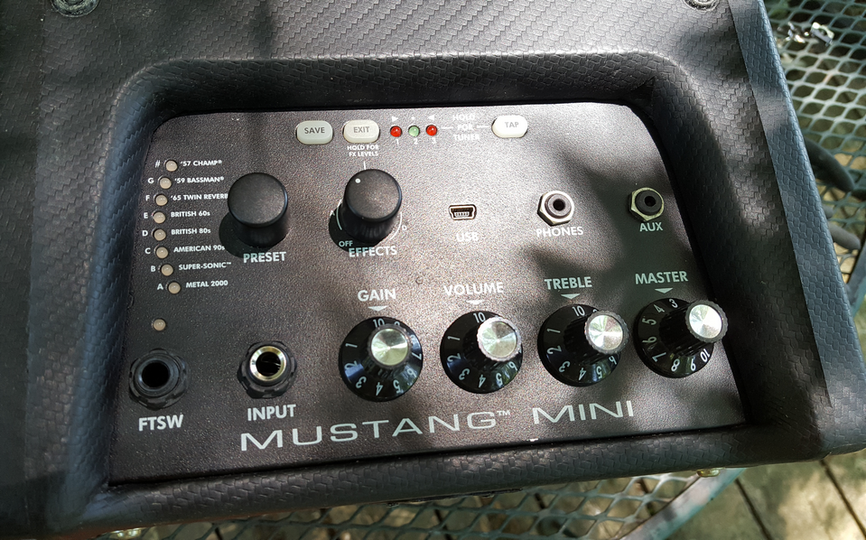
Initial testing consists of me using my partcaster (Neo Classical Strat), my Fender Mustang Mini, a Danelectro Zero Hum power supply and hoping nothing within the circuit goes boom. I then plug it all up to make sure that signal is passing in bypass mode with a few chords from Neo ringing through the Mustang Mini. Once I feel I'm ready I click the footswitch and prepare for excitement, or crushing, frustrating defeat. Again, one of the most common mistakes I've made is wiring related. I've wired potentiometers in backwards, I've mixed up the input and output, I've forgotten to ground the input and output, etc. I won't say always, but a large percentage of my guitar pedals work first try and are good to move on to final testing. Some circuits however are either using test parts or aren't giving me exactly what I expected from them, which causes them to be put into troubleshooting mode.
Troubleshooting or Parts Testing
Usually a simple wiring swap cures what ills a pedal, but sometimes it doesn't. If a circuit sounds different than I was expecting I will go through the comments under the layout on tagboardeffects and see if anyone else is having the same problem, where I will often find the solution. The comments section on that site is actually just as useful as the layouts themselves. Honestly, it's a great site. If I'm testing parts I will swap them around until I find what sounds best and (remember!) solder them into the socket to make sure they don't wiggle loose down the road and stop the pedal from working mysteriously. I only solder transistors or JFETs into their sockets as thus far I've not had any issues with op amps or other ICs wiggling loose, but that doesn't mean it can't happen.
Final Testing
Once a pedal is tested thoroughly and put through its paces with the Mustang Mini I switch over to the true lie detector, Kali, my 1960s Kalamazoo Model 1 tube amp. I've found a few circuits work perfectly fine through the Mustang Mini, but sound rather dull and lifeless through Kali. In the case of my treble boost build I found it worked great on the Mustang Mini, but Kali absolutely hated it, which caused me to rethink and adjust some of my modification choices. Kali is the final word when it comes to my guitar pedal builds as she is truthful, unabashedly so. I give her a few minutes for her tubes to warm up, I plug the pedal and guitar in and see how she sings. If a pedal and Kali can make a connection I can usually find a groove that allows me to test the range of the pedal's controls and once I'm satisfied with that I consider the pedal to be officially done.
Finalization
In every pedal I've built I've handwritten on the inside of the bottom case (lid?) the date the pedal was finalized, what I've named it, or what it's a clone of, and marked it with my faux brand Firebeard FX. I plan to get little boxes for each one and include a small printout explaining what the controls do and what it's based on. I've never painted any of my pedals, though I've wanted to. I'm perfectly fine with them as they currently are, which is functional and complete. That, to me, is when a guitar pedal build is finalized.
My thought is that someday I will cease to exist on this planet and only my former belongings and social media will remain. Someday someone might happen upon one of my creations and perhaps fall in love with it, making it a key part of their tone. Hopefully due to curiosity more so than needing to repair it, they will open the pedal and find my handwritten description of the pedal and the date it was built. They might take it a step further and research who Firebeard FX was and be directed to my social media, perhaps sending them on a grand adventure in understanding more about the pedal's creator and the process and care that went into creating it. As I'm writing this I have built thirty pedals in total and I honestly don't want to stop, I just need more reasons to build more pedals beyond sustaining a hobby I thoroughly enjoy (all except that damn wiring!). I would like to build a guitar amp, but that's almost entirely wiring. Ugh!
If you're thinking about getting into the hobby, or already are, and this has helped you, thank you for reading. It really is a fun, fulfilling hobby and I'm glad I took that first step in building my first Bazz Fuss. Trust me, it does get easier the more you build. Also, try to learn as much as you possibly can about what part does what and why when you build a circuit. Who knows, maybe someday we'll start a real pedal company once we understand enough about pedal circuits and how to build our own. It would be nice, no?